Zombie Snack... a simple game, inspired by some of the dice-roll combat games of years gone by. Eat brains, impress the ladies.
Two buttons..
Button One (digital 2) is EAT, which sends you after your human prey.
Button Two (digital 3) is RUN, which chooses to walk away.
You have fifty hit points to kill and eat as many humans as you can, but humans vary in strength and they fight back! If you reach zero hit points before you walk away, you die.. and score zero brains, no matter how many you had eaten until that point. The goal is simple.. eat as many brains as you can while still having enough health to walk away!
Choose when to EAT and when to RUN carefully!
Press RESET to play again.
Potential future enhancements: Multiplayer, High Score Retention, and Specials (powerups for both Zombies and Humans!)
Full Code (in blue):
// ** Zombie Snack 1.0 **
// by Paul Bishop
// 12/27/2010
// --------------------------------
// A Brain-Munching Game for
// Arduino. Program assumes
// 16x2 LCD connected on digital
// lines 7-12, and button switches
// on digital 2 & 3, ideally with
// 10k pulldown resistors (below)
//
// 10k Ohm
// Pin >----+---/\/\/\-------GND
// |
// SWITCH
// |
// +-----/\/\/\-------5v
// 100 Ohm
//
// LCD pins may be changed, but switches
// drive interrupts and must be on pins 2 & 3.
//
// Button connected to Pin 2 : "Eat"
// Button connected to Pin 3 : "Run"
#include <LiquidCrystal.h>
LiquidCrystal lcd(7, 8, 9, 10, 11, 12); // 4-bit mode for LCD
byte c1[8] = {
14,14,4,14,17,4,10,27}; // bitmap for human
int human;
int brains=0;
int hp=50;
int i,j,k=0;
int z;
volatile byte eat_press=0;
volatile byte run_press=0;
int action;
void setup() {
pinMode(3,INPUT); // Input is two buttons,
pinMode(2,INPUT); // "Eat" and "Run"
digitalWrite(3,HIGH); // Enable pullup resistors
digitalWrite(2,HIGH); //
attachInterrupt(0, eat, RISING); // handling buttons via ISR
attachInterrupt(1, run, RISING); // simplifies timing
randomSeed(analogRead(0)); // Seed random number gen
lcd.begin(16, 2); // set up the LCD's number of columns and rows
lcd.clear(); // and set our preferences
lcd.noAutoscroll();
lcd.noCursor();
lcd.createChar(0, c1); // 5x8 character bitmap from c1
lcd.setCursor(0, 0);
lcd.print("Zombie Snack 1.0"); // Splash screen.
lcd.setCursor(0, 1);
lcd.print(" Come-n-Get It!");
delay(3000);
}
void loop() {
lcd.setCursor(0,0);
lcd.print("Brains:");
lcd.print(brains);
lcd.print(" HP:");
lcd.print(hp);
lcd.print(" ");
lcd.setCursor(0,1);
lcd.print(" ");
lcd.setCursor(0,1);
lcd.print("Human! ");
for (int k=0; k<6; k++) {
lcd.setCursor(8,1);
for (i=0; i<k; i++) {
lcd.write(32);
};
lcd.write(0);
delay(100);
if (eat_press==1) {
attack();
};
if (run_press==1) {
game_over();
};
};
for (int k=5; k>-1; k--) {
lcd.setCursor(8,1);
for (i=0; i<k; i++) {
lcd.write(32);
};
lcd.write(0);
lcd.write(32);
delay(100);
if (eat_press==1) {
attack();
};
if (run_press==1) {
game_over();
};
};
}
void eat()
{
eat_press=1;
}
void run()
{
run_press=1;
}
void attack()
{
lcd.clear();
lcd.print("Zombie Attack!!");
randomSeed(analogRead(0));
human=random(10)+1;
lcd.setCursor(0,1);
lcd.print("Human- ");
lcd.print(human);
lcd.print(" hp!");
delay(3000);
while (human>0) {
lcd.clear();
lcd.print("Attack!!");
lcd.setCursor(0,1);
lcd.print("HP:");
lcd.print(hp);
lcd.print(" ");
for (k=0; k<(10-human);k++) {
lcd.print(" ");
};
for (k=0; k<human; k++) {
lcd.write(0);
};
action=random(2)+1;
if (action==1) { // Yeah! You Hit the Human!
lcd.setCursor(0,0);
lcd.print("CHOMP! Human -1");
human=human-1;
if (human==0) {
delay(500);
lcd.clear();
lcd.setCursor(0,0);
lcd.print(" Human Dead!");
lcd.setCursor(0,1);
lcd.print(">>> BRAINS! <<<");
brains=brains+1;
delay(2000);
};
};
if (action==2) { // Ouch! You got hit!
lcd.setCursor(0,0);
lcd.print("OUCH! Your HP -1");
hp=hp-1;
if (hp==0) {
game_over();
};
};
delay(1000);
};
eat_press=0;
lcd.setCursor(0,0);
lcd.print("Brains:");
lcd.print(brains);
lcd.print(" HP:");
lcd.print(hp);
lcd.print(" ");
lcd.setCursor(0,1);
lcd.print(" ");
lcd.setCursor(0,1);
lcd.print("Human! ");
}
void game_over()
{
run_press=0;
lcd.clear();
if (hp==0) {
brains=0;
lcd.setCursor(0,0);
lcd.print(">> You Died! <<");
lcd.setCursor(0,1);
lcd.print("Brains: 0");
}
else
{
lcd.setCursor(0,0);
lcd.print("Good Ghoul!");
lcd.setCursor(0,1);
lcd.print("Brains Eaten: ");
lcd.print(brains);
};
while (1) {
}; //loop forever
}
Monday, December 27, 2010
Friday, November 19, 2010
Schematic- Arduino Spectrum Analyzer
Arduino Spectrum Analyzer with Video Out - Schematic

Components:
(1) 2n3904 NPN Transistor [Q1]
(3) 1k Ohm Resistor [R2,R4,R5]
(1) 330 Ohm Resistor [R6]
(1) 10k Ohm Resistor [R1]
(1) 100k Ohm Resistor [R3]
(1) Electrolytic Capacitor, 3.3MF [C1]
(1) Electret Microphone [MIC1]
Video out is NTSC/PAL Composite, if necessary a coupling capacitor and diode can be added.
The code for this version is on the previous blog entry, a revised version of both the code and the circuit will be posted within the next several days, as the TVout library is being re-released with significant changes which make compatibility with this setup a problem. I'm waiting on releasing the new code and circuit until the library author's release, to avoid confusing folks.
Sunday, November 14, 2010
Arduino Realtime Audio Spectrum Analyzer with Video out!


Once again, I decided to put the old travel DVD player's screen to good use by using as an output device for the Arduino. Though the DVD mechanism is broken, the screen allows for standard NTSC composite video input.. runs on an attached rechargeable battery pack (can also power the Arduino.)
I make no guarantees, and you do so AT YOUR OWN RISK, but it should work with any TV or device that allows NTSC Video In. I am in no way responsible if you damage yourself or your equipment. This is a prototype built by an amateur, keep that in mind.
A brilliant bit of code, the TVout http://www.arduino.cc/playground/Main/TVout library for Arduino, allows you to generate composite NTSC monochrome video with only two pins and two resistors. I generally leave the resolution at the default 128x96, which translates to 16x12 text with the default 8x8 font. Running under the defaults seems to give the least amount of trouble with this library, which is a work in progress. Note that due to this library being actively worked on, there's no guarantee the code I am using will work with other IDE or Library versions. This has been developed using version 0019, though I will be testing shortly on the most recent releases. In addition, though it should not matter, I am using a 5v Adafruit Boarduino. There should be no differences, as long as your Arduino is a 5v device. Also note that old versions of Arduino which use an Atmel ATmega168 won't be able to run this, they don't have enough memory.
The other piece of the puzzle is collecting and processing audio, so we have something to display on our little display.
The first piece- data collection- is fairly standard. I use an electret microphone (which alone only produces a few mV output, far too low for our Arduino to use directly) with a transistor amplifier as the signal source, which is then sampled via the ADC on the Analog 0 pin of the Arduino.
To do spectrum analysis however, you need to capture signal over time, then process that data with what is known as a Fourier Transformation. This magical process takes a signal and breaks it down into buckets based upon frequencies found within the sample. This produces a remarkably good picture of the signal.. and if displayed, functions as a visual spectrum analyzer if looped over and over.
In this project, I've used code posted by a user to the Arduino forums:
http://www.arduino.cc/cgi-bin/yabb2/YaBB.pl?num=1286718155.
This post contains a library which performs both the sampling and the Fast Fourier Transformation completely in C in 8 bits, amazing fast considering that fact, and uses a few tricks to be really stingy on memory, which is at a premium on Arduino- especially with the TVout data space eating up quite a bit. Since the Atmega 328 only has 2k of RAM, every byte counts. Matrix math done like this is nothing short of awesome. Best of all, it's usable as a library. Cut and paste the .cpp and .h into a new folder named "FFT" in the Libraries directory. My Arduino project code is adapted from the original code from the forum-posted Arduino program.
So, to produce our desired outcome, we just need to get to get the whole show together and hope it can perform.. With only a handful of cheap components (a few dollars at most), it produces a perfectly usable and quite entertaining realtime 64-band video spectrum analyzer. Though not really "useful" for any real purposes, it makes an entertaining party display out of any television with a video input...
Arduino Code:
#include <TVout.h>
#include <fix_fft.h>
TVout TV;
char im[128], data[128], lastpass[64];
char x=32, ylim=90;
int i=0,val;
void setup()
{
TV.begin(_NTSC,128,96); // Initialize TV output, 128x96.
TV.print_str(2,2," Realtime Arduino"); // TVout lib uses x,y for print
TV.print_str(2,11," Spectrum Analyzer"); // statements. 8x8 default font.
analogReference(DEFAULT); // Use default (5v) aref voltage.
for (int z=0; z<64; z++) {lastpass[z]=80;}; // fill the lastpass[] array with dummy data
};
void loop()
{
for (i=0; i < 128; i++){ // We don't go for clean timing here, it's
val = analogRead(0); // better to get somewhat dirty data fast
data[i] = val/4 -128; // than to get data that's lab-accurate
im[i] = 0; // but too slow, for this application.
};
fix_fft(data,im,7,0);
for (i=1; i< 64;i++){ // In the current design, 60Hz and noise
data[i] = sqrt(data[i] * data[i] + im[i] * im[i]); // in general are a problem. Future designs
TV.draw_line(i+x,lastpass[i],i+x,ylim,0); // and code may fix this, but for now, I
TV.draw_line(i+x,ylim,i+x,ylim-data[i],1); // skip displaying the 0-500hz band completely.
lastpass[i]=ylim-data[i]; // if you insist, initialize the loop with 0
}; // rather than 1.
};
The circuit required is a simple microphone and transistor amplifier, as well as two resistors connected to D8 and D9 to provide video signal. See the next blog post for the schematic.. drawing is a much bigger pain than you'd think!
Friday, August 13, 2010
Fiat Lux! (Let There Be Light)
Since I wasn't up to retesting the HDR function at Wayside today, I've decided to do a little bench work and incorporate a light sensor. It seems that light-based triggers are a common project for people interfacing a camera to a microcontroller, and for very good reason.. both infrared and visible light triggering can be very useful in photography. No exceptions here, and we're going to use a very simple and flexible interface which will allow for use of several types of sensors with minimal headaches.
The circuit itself really could not be more simple:

Basically, we're just going to create a voltage divider. Think of it this way: the balance between adjustment resistor and the sensor controls how much of the 5 volts goes to the analog port and how much gets dumped to ground. We'll use a variable resistor (a potentiometer) for the Adjustment Resistor, to obtain some working values. This adjustment resistor will account for varying response curves of various components, and allow us to tweak our build a bit. We'll be coming back to that adjustment resistance in the future.
For our first run at this, I'll use an Infrared Phototransistor. This is sold by Radio Shack as part of an emitter/detector pair with part number 276-0142. I try to use very common and inexpensive components.. nearly any part I use is available at Radio Shack or other hobby electronics retailers. Keep the emitter around, we'll be having some fun with that too. Virtually any phototransistor will work, they just vary in terms of sensitivity and frequency range.
The phototransistor from the Radio Shack emitter/detector pair is about as basic as you can get, peaks out sensitivity-wise around 850nm, and is easy to use. Simply put, configured as we have got it, the phototransistor will allow a varying voltage to reach the microcontroller's Analog Pin 0 based upon the amount of light falling on it. For the initial value of the adjustment resistor, I had a 15k ohm handy, which was enough for starters. The 15k resistor was replaced with a potentiometer to judge the effects with a number of different sensors, as we'll see.
Now all we need is a little code to test it out. Happily, the Arduino IDE has "AnalogInSerialOut" as the first sketch in the code snippet library. We'll just load that up and open the Serial monitor to see the values being produced. That's all the usefulness we'll get from the sketch at the moment, but it's an easy interface to visualize the data so you can test. Of course, you can write your own sample-and-send-to-serial sketch also.. but I am tremendously lazy and am happy with kludges as long as they work. For reference, a "kludge" is a term used to discuss technical solutions which are by no means pretty or the right way- but they work. In some ways, Arduino is a huge kludge- it'll get the job done, but a purist may look on with disgust because we aren't developing in Assembler. In the end, if our project works.. it's the right answer, in my opinion. Maybe if this were a commercial product, but I see no reason to make life any harder than we have to for ourselves.
Thursday, August 12, 2010
HDRduino Test Drive!
 |  |  |
 |  |  |
Source Photos, Wayside Inn, Sudbury MA. Shots taken at 28mm f/29 | ||
Success! (of a sort). The six images above were produced using the Arduino-based HDR trigger we built and programmed last time. Of note was the fact the fastest shots were not picked up or taken reliably, of the nine shots triggered, only seven were taken by the camera itself. Consequently, we're successfully tested our HDR trigger, what's more, we've discovered that it may not perform quite as quickly as we had hoped. In addition, in retrospect, Wayside Grist Mill may not be the best choice, simply because the water wheel is in motion and becomes motion-blurred in longer shots. Note that we could account for that in editing, but for the moment, we're mainly concerned about the overall function.. and it did what we wanted it to do- took a series of bracketing exposures.
If you are doing this yourself, the camera needs to be set up in Manual mode, with the shutter duration set to "bulb"- which basically means externally controlled (by our trigger, at the moment). The scene is focused and a very small aperture is set on the lens- for this example, I used the smallest available aperture on my kit EF-S 18-55mm lens, f/29. Using a small aperture helps to maintain a deep field of focus, as well as allowing for longer exposure times. Once the scene is focused the lens is then placed in Manual focus mode, to prevent the lens from wasting time hunting for focus, especially since it will be a static scene. If we've focused once, it'll remain in focus during our time shots.
If you are doing this yourself, the camera needs to be set up in Manual mode, with the shutter duration set to "bulb"- which basically means externally controlled (by our trigger, at the moment). The scene is focused and a very small aperture is set on the lens- for this example, I used the smallest available aperture on my kit EF-S 18-55mm lens, f/29. Using a small aperture helps to maintain a deep field of focus, as well as allowing for longer exposure times. Once the scene is focused the lens is then placed in Manual focus mode, to prevent the lens from wasting time hunting for focus, especially since it will be a static scene. If we've focused once, it'll remain in focus during our time shots.
Given the simplicity of the project, we shouldn't be displeased with the outcome. For processing, I chose ENFUSE!, with it's accompanying GUI. This is an Open Source software, and can be downloaded and used for non-commerical purposes under a GPL license. I processed the photos with the default software options, producing the HDR photo below. Now I'll agree it's probably not the most impressive HDR shot ever, however it does demonstrate that we're on the right track. We'll do some more shots after we address a few of the problems found, and see if we can get a little better at tweaking the software too. What's important to notice is that the HDR photo has uniform exposure across the entire scene- the brightness of the green trees in the foreground is lost in the "best" shot above, when the Mill is exposed well, leaving them underexposed. Conversely, some of the finer details are also lost to overexposure. The composite, or "High Dynamic Range" photo merges the exposures in an attempt to display all portions of the scene exposed properly.. at least that's the theory. In practice, it does a remarkable job at just that.. especially since this was our first attempt.
 |
| Composite "HDR" Photograph produced from source photos, above. |
Now, let's consider the other information learned:
Two images were dropped, we'll assume they were the first two, due to short duration...Of the seven shots, the first two are so similar in exposure we have to assume we merely hit minimum exposure time on the longest. If we use "Mirror Lockup" mode we may gain some speed, so it appears somewhere near 1/100 second may be the fastest we'll get via shutter port (I'm using my Canon Rebel XT, for reference).
Since we basically are saying the first three shots are being wasted, time wise, we're going to change our timing to begin at 1/100 second, as well as lock up the mirror in an attempt at getting just a little bit faster response. Eventually, we may move off of the shutter port and use USB to control the camera in much more precise a manner, but before we begin the rather painful undertaking of writing a USB host, we're going to explore and exploit the control we've gotten this far.
It's important to note that any camera that has the ability to be remotely triggered will work with this device also, simply modify the plug to match the connection for your camera, as long as what's required is a simple switch-closure to operate the shutter.
As always, you probably void your warranty by connecting something like this to your camera-- anything you do, you do at your own risk!
Here's our updated code.. we'll set up for seven shots now, with a minimum of 10ms (1/100sec).. otherwise everything remains the same.
int shotcount = 7;
int shutterPin = 5;
long mintime = 10;
long delaytime;
void setup()
{
pinMode(shutterPin, OUTPUT);
Serial.begin(9600); // setup to communicate by serial
}
void loop()
{
Serial.print("Sequence: "); // provide info by serial, if wanted
Serial.print(shotcount);
Serial.print(" shots, minimum ");
Serial.print(mintime);
Serial.println(" ms.");
int i=0;
delaytime=mintime;
while (i < shotcount)
{ // loop until we take all the shots
Serial.print("shot duration: "); // report out on serial line
Serial.print(delaytime);
Serial.println(" ms.");
digitalWrite(shutterPin, HIGH); // open the shutter
delay(delaytime); // wait for the exposure time
digitalWrite(shutterPin, LOW); // close the shutter
delay(2000); // wait two seconds for camera
delaytime=delaytime*2; // double duration for 1eV step
i=i+1;
};
Serial.println("Sequence Complete!");
while (1) {}; // Wait forever
}
Next time, we'll give our trigger another try with the new code, as well as look at how our Arduino looks at things...
It's important to note that any camera that has the ability to be remotely triggered will work with this device also, simply modify the plug to match the connection for your camera, as long as what's required is a simple switch-closure to operate the shutter.
As always, you probably void your warranty by connecting something like this to your camera-- anything you do, you do at your own risk!
Here's our updated code.. we'll set up for seven shots now, with a minimum of 10ms (1/100sec).. otherwise everything remains the same.
int shotcount = 7;
int shutterPin = 5;
long mintime = 10;
long delaytime;
void setup()
{
pinMode(shutterPin, OUTPUT);
Serial.begin(9600); // setup to communicate by serial
}
void loop()
{
Serial.print("Sequence: "); // provide info by serial, if wanted
Serial.print(shotcount);
Serial.print(" shots, minimum ");
Serial.print(mintime);
Serial.println(" ms.");
int i=0;
delaytime=mintime;
while (i
{ // loop until we take all the shots
Serial.print("shot duration: "); // report out on serial line
Serial.print(delaytime);
Serial.println(" ms.");
digitalWrite(shutterPin, HIGH); // open the shutter
delay(delaytime); // wait for the exposure time
digitalWrite(shutterPin, LOW); // close the shutter
delay(2000); // wait two seconds for camera
delaytime=delaytime*2; // double duration for 1eV step
i=i+1;
};
Serial.println("Sequence Complete!");
while (1) {}; // Wait forever
}
Next time, we'll give our trigger another try with the new code, as well as look at how our Arduino looks at things...
Wednesday, August 4, 2010
HDRduino v1.0
Last time, we fiddled with the Arduino, exploring the basics of what we need to do- essentially, open and close a switch in a sequenced and time-precise manner. This time, we're going to take the finished prototype, write the first version of the software, and give it a try.
To begin, the circuit we'll be using is very simple- a single resistor and an optical isolator to protect our equipment from damaging voltages. The first version has no interface to the user- you plug it into the camera, set the camera to the aperture and focus you need, and turn on the Arduino. It will run through the program we write once, then put itself into an endless loop doing nothing until we remove power. Later I'll be putting this in a case of some sort, and adding at least a power switch. Until then, we'll simply connect the battery once everything else is in place. Not the most elegant solution, but I had no reasonable switches at the moment and we're only prototyping. Doing things like this is not really recommended- but if you are like me, you'll try to find a way to make do with what you have got.


Assembled prototype, with 9v battery for power. The Arduino's onboard 5v regulator (seen just above the power plug in this photo) happily produces clean 5v for quite some time from a standard 9v battery. The tip and shield contacts from the 2.5mm plug go to the optoisolator output, which acts as a switch. Canon remote shutter releases are nothing more than pushbutton switches connected between these contacts. To make prototyping easier, the wires from the 2.5mm plug were soldered onto three breadboard header pins and then secured together with a dab of epoxy for a bit of mechanical strength.
The code we'll use this time includes reporting of the trigger's status via the serial port, mainly for troubleshooting purposes- however, since the overhead is small, I try to include some status outputs from my code to both illustrate it's function as well as potentially provide usable information. A running status feed is sometimes very useful to have.. and also allows others to use those feeds for their own purposes. Making ways for others to piggyback on your work is always a good idea in my book.
int shotcount = 9; // Hardcode for 9 shots for now
int shutterPin = 5; //
long mintime = 4; // Try for 1/250sec min exposure
long delaytime;
void setup()
{
pinMode(shutterPin, OUTPUT);
Serial.begin(9600); // setup to communicate by serial
}
void loop()
{
Serial.print("Sequence: "); // provide summary info by serial
Serial.print(shotcount);
Serial.print(" shots, minimum ");
Serial.print(mintime);
Serial.println(" ms.");
int i=0;
delaytime=mintime;
while (i < shotcount) {
Serial.print("shot duration: "); // dump shot info to serial
Serial.print(delaytime);
Serial.println(" ms.");
digitalWrite(shutterPin, HIGH); // open the shutter
delay(delaytime); // wait for the exposure time
digitalWrite(shutterPin, LOW); // close the shutter
delay(2000); // wait two seconds for camera
delaytime=delaytime*2; // double duration for 1eV step
i=i+1; // go on to the next shot
};
Serial.println("Sequence Complete!");
while (1) {}; // Wait forever
}
When we upload the program to the Arduino and open the Serial Monitor (which displays the information the Arduino sends on the serial port), we get the following output over a period of about twenty seconds total. Power cycling or pressing the Reset button on the Arduino produces the same. If we assume the remote shutter hardware works properly, the results should be a series of nine photos, starting with a 1/250sec exposure and finishing with a 1 second exposure (1.024 seconds actually).
Sequence: 9 shots, minimum 4 ms.
shot duration: 4 ms.
shot duration: 8 ms.
shot duration: 16 ms.
shot duration: 32 ms.
shot duration: 64 ms.
shot duration: 128 ms.
shot duration: 256 ms.
shot duration: 512 ms.
shot duration: 1024 ms.
Sequence Complete!
A few remarks: First that the minimum exposure of 4ms may not fully work. This is because it's been reported the fastest speed one can trigger on the shutter release is around 5ms which is 1/200sec. This minimum therefore will either work to produce a 1/250sec exposure, or as close as we'll get. As I understand this may be able to be reduced by using "Mirror Lock Up" function on the camera- but we'll worry about camera settings in a little while, after we get the trigger working. Additionally, since I am simply doubling the exposure time at each interval, we're not getting "true" standard exposure times.. but not too far off to make them unusable. In terms of exposure, there's little difference between a second and 1.024 seconds.
This all being said, when plugged into the shutter release port on the side of my Canon Rebel XT and powered up, the camera began dutifully clicking away under the command of the little Arduino.
Arduino II.. A blinky light, and then something useful!
Last time, I introduced the Arduino platform and the version of it that I am using, a "Boarduino" from Adafruit Technologies. In function, all of these devices are very similar. For my purposes I decided to go with the Boarduino simply because the vendor was local and I could get it quickly, as well as offering a basic set of extra components for experimentation.
I will suggest that folks who are completely new to microcomputers and interfacing go for the "true" Arduino at the outset. The reason is simply that the support community and software out there focus on the Arduino as the common ground.. therefore "everything" works on the Arduino, while some variants (such as mine, the Boarduino) might require a little bit of tweaking to work properly. For me, this was a fun challenge- for some it might have been discouraging. In the end, to work with the latest version of the programming environment, I needed to select the device as a "Lilypad 328" and edit the file to properly reflect the 16Mhz CPU clock rate. That's something a novice wouldn't know to do, and had I been working with "true" Arduino hardware, the problems I had would not have been there in the first place. This being said, I truly am happy with my choice of the Boarduino, and think that there's room for both the off-the-rack Arduino and the Boarduino in my toolbox. The Boarduino is cheaper, simpler, and easy to incorporate into a finished project.. the Arduino is good for development, as it is the gold standard of the platform. From here on, I will refer to the Boarduino as an Arduino, as in all aspects that matter in terms of this project, they are functionally equivalent. I won't give a complete tutorial on the Arduino programming language, there are a number of them available online. If you are using this blog to construct a similar device, I also assume that you have gotten an Arduino of some flavor, and have successfully connected to it.
If you decide to get an Arduino, the first thing you are going to do is make a blinky light. The reason is quite simple.. the most basic demonstration program for the Arduino is "Blink"... which blinks the LED on the Arduino off and on once a second. This is about as basic a program as can be written that actually DOES something, if you can call using hours of work and thirty dollars to do something that you can do with a $1.99 component from Radio Shack (blinking LED's are cheap) "something". This of course should not stop you from being proud that you did it. Here's the program, with the program comments changed.. this is the original "Blink" code included as an example program in the programming environment. A double slash "//" indicates the rest of the text on a line is a comment.
int ledPin = 13; // The arduino has an LED on pin 13. This requires no external wiring.
void setup() // When the arduino starts up, the setup() routine is run once
{
pinMode(ledPin, OUTPUT); // Tell the Arduino we plan to use the LED pin for output.
}
void loop() // The loop() routine runs over and over as long as the unit has power.
{
digitalWrite(ledPin, HIGH); // set the LED on
delay(1000); // wait for a second
digitalWrite(ledPin, LOW); // set the LED off
delay(1000); // wait for a second
}
When this program is downloaded to the Arduino, sure enough, the LED blinks off and on, once a second. The program itself shows the simplified "C" language structure used, as well as what will be the most heavily used functions in control projects.. the ability to turn a pin output off and on, and the ability to implement precise enough delays to control external things, in my case, a camera. The program is simple enough for nearly anyone to understand and modify.. for example, if you were asked how to make the blink rate two seconds, it's not hard to figure out that would be done by changing the delay(1000) to delay(2000). (the delay command takes milliseconds, thousandths of a second, as it's parameter.) "Blink" is an excellent program to fiddle with, to learn a little. Try setting the "on" period to two seconds, with a half a second "off" period. The Arduino is "for" fiddling and learning, go ahead and fiddle and learn. Just don't admit in public just how much time you were able to amuse yourself by making a blinking light..
Blink is the core of what I will be doing- controlling external hardware based upon timing. The first project for the camera, an HDR Photography shutter trigger, is scarcely more complex, only adding some changing delays to handle a range of exposures.
HDR, or High Dynamic Range photography, is a process that is the natural extension of a photographic process known as bracketing. When a photo is taken, due to the nature of light, certain parts of any scene will be overexposed, some underexposed, and hopefully most will fall into the middle "correct" exposure. Bracketing simply means taking extra pictures, intentionally underexposing and overexposing on the extras- with the end result being that between the shots, ALL parts of the scene will have been properly exposed. These shots are then combined to produce a single image, with correct exposure levels on all parts of the scene. Sometimes aspects are manipulated for artistic effect, but often, the effect of HDR in general is both beautiful and surreal without taking liberties. Most higher-end consumer cameras and all professional cameras can do single bracketing, taking one shot above and below in terms of exposure, as a function. This project will do full-range bracketing for two ranges.. daylight and night. To do this, we lock the camera in terms of aperture and focus, and simply use the shutter "bulb" mode controlled by the Arduino via the remote control port on the camera. Via the shutter remote port, we can get speeds as fast as 1/200 second, which should be usable in the aperture ranges we will use.. typically f8 to f11- because at small apertures, the "in focus" depth of field will change little as the shutter time changes. Our little Arduino's job will be to open and close an electronic "switch" at the proper intervals to take the series of time shots to produce up nine bracketing images, across the entire range of exposures.
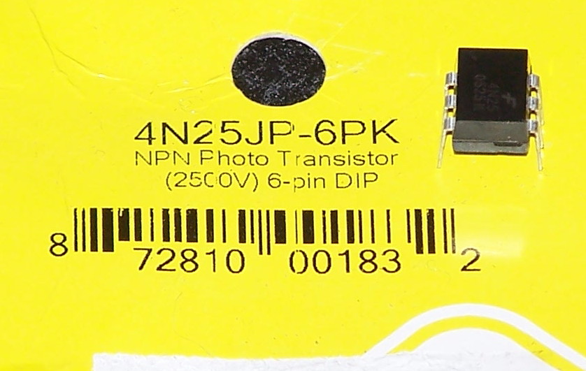
There are a number of methods that could be used to change the digital output of the Arduino into the switch-type behavior we want- but for the sake of doing it "the right way" and protecting external equipment (like my camera), either a relay or an optical isolator puts an electronic barrier between your circuit and what you are controlling.. protecting both in the process. Relays introduce a certain amount of delay, draw quite a bit of current, and are more expensive- so I've chosen optical isolators. I was able to get a pack of six for three dollars from a local electronics store, Radio Shack also sells comparable ones. I'll be using Fairchild 4N25 Optoisolators. Aside from a couple of wires and a 2.5mm phono plug (Canon's remote trigger plug is simply a 2.5mm stereo plug) all we need is one of these optoisolators and a single resistor.
If you question the need for the isolator, as I have been experimenting, I was triggering a flash unit which was faulty and backfed nearly 2000 volts into the circuit.. and the Arduino was still also connected to the PC at the time. Had the optoisolator not been in place, that voltage could have ended up frying both the Arduino and even potentially my PC. The fault cost me a fifty cent isolator, and convinced me to isolate as much as I can, to avoid problems!
 Note: Connecting anything to your camera other than approved hardware probably voids the warranty! I am an experimenter and do not accept responsibility if you damage your equipment. If you are looking for a no-risk finished product, there are commercial products which perform these functions without the risks. This blog is for folks aware of the risks of prototyping hardware- I try to design well, but I provide no warranty as to the safety or usability of any project!
We'll be using Digital Pin 5 as the shutter control pin, as later on, we'll be using other pins for other functions. Next time, we'll upload our first version HDR program to the Arduino, plug it in, and see if we can get some useful shots!
Friday, July 23, 2010
Adowhatnow? (Arduino and Atmel AVR Twiddling) : What is it?
Adowhatnow? Your Humble Narrator introduces the backbone of several projects.
Boarduino kit, Assembled. The birth of a new machine.
 Boarduino kit, purchased locally but designed and sold by Adafruit. The local seller is actually a college student who is an avid fan of the Arduino/Atmega platform. In addition to the components and board for the Boarduino itself, included was a kit-form interface card to allow a home computer to communicate with it via a PC serial port, a solderless prototyping breadboard, and a small assortment of components (LED's, resistors, etc) to start out with.
 Assembled Boarduino parked happily on the breadboard. Online assembly instructions for the module were fairly good, and would be able to be read and followed by a high school student with relative ease. Even before I first powered it, I've decided this module would make an EXCELLENT project for any tech-minded teen. Not only is the kit manageable, the module, when done, opens worlds of experiments for an inquisitive and creative mind.
 Boarduino module, along with assembled "Wulfden P4b" Serial-to-TTL communications board. This board allows for programming of and communication with the Boarduino via a home computer. Though useful as a computer interface, the module's real strength is that once programmed, the module only requires a battery to operate.. making it a totally portable, extremely low-power computing and control platform, perfect for small projects at low cost. Though small, this module is substantially more powerful a computer than several of the first home computers I owned.
 Solder-pad/header side of the Adafruit Boarduino module and Wulfden P4b Serial-to-TTL interface. The total assembly time for the two boards was about two hours, including needing to desolder and resolder one component I installed incorrectly the first time. For the electronics folks, I can say I am very pleased with the pin header layout- the fact that the module is designed for breadboarding is really apparent, with all signals and connections readily available.
"Arduino" is an open-source set of hardware and software designed around the ATMEGA series of microcontrollers. These are entire computers contained within a single chip.. with one of these chips, and a small number of external components, you have the framework for complex electronic projects and intelligent devices. It's intended to be used by people not normally interested in getting their hands dirty in the inner workings- artists (kinetic sculptures), robot builders, students, and prototyping hobbyists. In short, it simplifies the process of creating a special-purpose "smart" device.
When referencing Arduino, many people refer to the entire package- the chip, the on-chip boot software, and the programming environment- as a single unit. In reality, nearly all aspects can be changed- the chips and hardware come in several flavors, as do boot software and the programming environment. To deviate from the "package" is fine, but with certain tradeoffs. Different flavor of hardware offer varying feature sets like memory size and operating speeds, while different development software platforms provide varying levels of programming ease traded off against efficiency. Development languages run the gamut- from simplified Firmata Scripting to Assembly Language coding (not for the faint of heart). There are even compiled and interpreted forms of BASIC which can be used. Because it provides a nice balance of simplicity and power, at least at the outset I will be using the Arduino development language, which is similar to "C" and based on a scripting language called Wiring. If you have ever done Java, Pascal, C++, or similar coding, then Arduino code should be easy to adapt to. Since this is mainly a command and control device, and we don't want to get too bogged down in syntax, the Arduino language and IDE will serve nicely while still keeping the code simple.. I'm a firm believer that keeping things simple makes for a better outcome. One nice aspect of the wide support base is that you can choose what you use- you don't need to change hardware if you change programming language and vice versa.
To start off, I chose a variant of the Arduino called a Boarduino. I chose this variant because it offered several benefits for me over the "Off the Rack" standard Arduino. First, the Boarduino came as a self-assemble kit, not a finished product. It's been some time since I had done much electronic assembly, and considered that a well-designed kit would give me some much-needed practice soldering and handling components, while still being a project needing only an hour or so of relatively simple work. Secondly, the Boarduino design minimizes the component count, minimizing the complexity. Lastly, the Boarduino is extremely inexpensive, with the module components totalling around $15 per module, making it reasonable to dedicate a module to a "permanent" project. The absolute minimum hardware implementation of the chip circuit can be had for under $10 on eBay and other online vendors as of July 2010. Though underpowered for some of the projects I intend, there are Atmel processors which scale down to an eight-pin chip selling for under $2 each which still maintains a substantial amount of the function contained in the Atmega328/Arduino platform. Conversely, Atmel and others produce similar but far more powerful devices at substantially higher cost also. For my purposes, the chosen platform offers a nice blend of power while still fitting into a Hobby budget.
Boarduino kit, Assembled. The birth of a new machine.
 Boarduino kit, purchased locally but designed and sold by Adafruit. The local seller is actually a college student who is an avid fan of the Arduino/Atmega platform. In addition to the components and board for the Boarduino itself, included was a kit-form interface card to allow a home computer to communicate with it via a PC serial port, a solderless prototyping breadboard, and a small assortment of components (LED's, resistors, etc) to start out with.
 Assembled Boarduino parked happily on the breadboard. Online assembly instructions for the module were fairly good, and would be able to be read and followed by a high school student with relative ease. Even before I first powered it, I've decided this module would make an EXCELLENT project for any tech-minded teen. Not only is the kit manageable, the module, when done, opens worlds of experiments for an inquisitive and creative mind.
  Boarduino module, along with assembled "Wulfden P4b" Serial-to-TTL communications board. This board allows for programming of and communication with the Boarduino via a home computer. Though useful as a computer interface, the module's real strength is that once programmed, the module only requires a battery to operate.. making it a totally portable, extremely low-power computing and control platform, perfect for small projects at low cost. Though small, this module is substantially more powerful a computer than several of the first home computers I owned.
 Solder-pad/header side of the Adafruit Boarduino module and Wulfden P4b Serial-to-TTL interface. The total assembly time for the two boards was about two hours, including needing to desolder and resolder one component I installed incorrectly the first time. For the electronics folks, I can say I am very pleased with the pin header layout- the fact that the module is designed for breadboarding is really apparent, with all signals and connections readily available.
So.. we have an assembled kit. What now? Stick around and see!
Subscribe to:
Posts (Atom)